The noise analysis, truncation and compensation are done after filtering, separately for each frequency band. Option 1 is the most accurate, and therefore recommended for most room impulse response measurements. However, it requires a measurement of reasonably high quality to give good results.
The crosspoint between the decaying response and the stationary noise floor is detected using an iterative algorithm [A. Lundeby, T.E. Vigran, H. Bietz and M. Vorländer, "Uncertainties of Measurements in Room Acoustics," Acustica, vol. 81, pp. 344-355 (1995)]. Subsequently, a truncation point is determined using a safety margin above the crosspoint. With the Noise floor margin parameter the user can specify in dB how far above the noise level at the estimated crosspoint the truncation point is chosen and integration shall start. Typical values are in the range 5 - 10 dB, the recommended value is 5 dB. Higher margins should be used only with responses with extraordinary high signal-to-noise ratios. The late slope of the truncated response is calculated by a line fit, and a compensation for the energy lost by truncation is estimated assuming exponential decay to infinity.
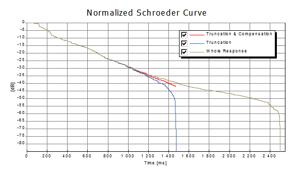
The decay curve forms the basis for calculation of the various decay time parameters, and it can be plotted using the Schroeder plot-type. The plots below give examples of the three options. If truncation is chosen, all room acoustical parameters involving the late part of the response is calculated based on a similarly truncated impulse response. If compensation is chosen and the truncated energy can be successfully estimated, all room acoustical parameters involving the late part of the response are corrected for the truncated energy.
If the truncation point cannot be determined due to too much noise or an odd shape of the response after filtering, no parameters will be calculated for that particular frequency band. If a response produces trouble, turning off truncation and compensation and inspecting the filtered impulse response and Schroeder curve might reveal the source of the problem.
The figure below gives an example of the three available options.
 Contents
 Index
Index Search
 Previous
 Next
Next