Go to Measurement->Calibration... and in the dialog box, click the Calibrate... button shown below.
You should now see the dialog shown below.
(A faster method of displaying this dialog box is to click
the  button on the
Standard toolbar.)
button on the
Standard toolbar.)
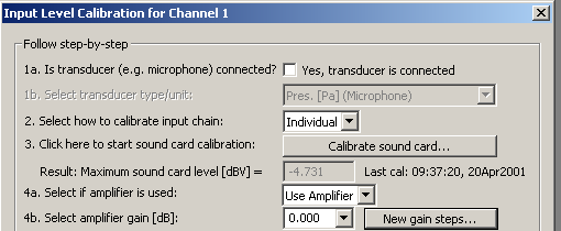
Follow this procedure step-by-step.
In step number 1a, make sure  is not checked.
In step number 2, select  . We select since
we will connect an external input attenuator/amplifier and want to be able to
adjust the gain steps of this device.
. We select since
we will connect an external input attenuator/amplifier and want to be able to
adjust the gain steps of this device.
Note that the number  shown in the figure above is updated after the calibration. It
gives you the maximum input level that WinMLS can measure (a higher level will
result in digital clipping). In this case it is 4.731 dBV.
shown in the figure above is updated after the calibration. It
gives you the maximum input level that WinMLS can measure (a higher level will
result in digital clipping). In this case it is 4.731 dBV.
In step number 3 click the  button shown below to start the
calibration.
button shown below to start the
calibration.
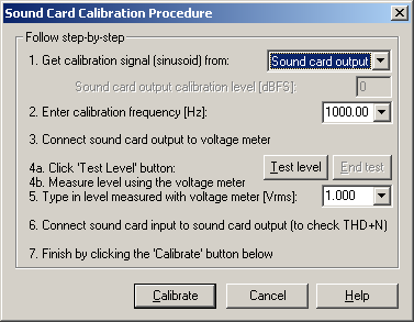
The dialog box shown below will be displayed (it may look different dependent on what type of calibration is selected).
Follow the procedure in the dialog shown above.
Note: In step 2 above it may give better results if you use 100 Hz instead of 1000 Hz because in general a voltage meter may be more accurate for 100 Hz.
You can click the  button (shown in figure above) to see if the input level is
acceptable. The WinMLS mixer dialog will pop up to give you the levels, if not,
you can also find the levels at the status bar found at the very bottom of the
WinMLS program
button (shown in figure above) to see if the input level is
acceptable. The WinMLS mixer dialog will pop up to give you the levels, if not,
you can also find the levels at the status bar found at the very bottom of the
WinMLS program  .
.
If the level is less than 30 dBFS, it should be increased. A warning will be given if this is the case when you perform the calibration and an explanation will be given on how you can increase the level.
Now connect a volt- meter to the sound card output and measure the Vrms level. Type the measured level in step number 5.
Click the  button to perform the calibration. This will exit the dialog box
if the calibration is successful. It takes a few seconds and afterwards a new
conversion factor and date and time for the calibration is displayed as shown
below.
button to perform the calibration. This will exit the dialog box
if the calibration is successful. It takes a few seconds and afterwards a new
conversion factor and date and time for the calibration is displayed as shown
below.
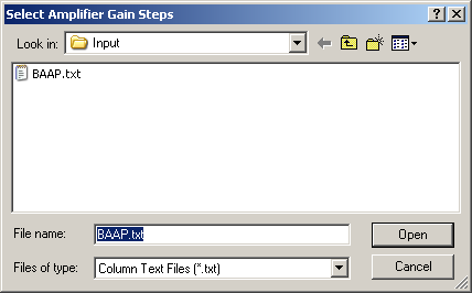
In step number 4b, click the  button to open the browse dialog
shown below.
button to open the browse dialog
shown below.
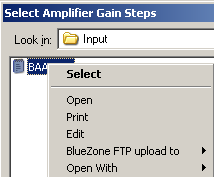
The file named BAAP is selected. It contains the gain steps for the active attenuator we sell. BAAP stands for Balanced Active Attenuator and Probe. You can open the file by right-clicking on it as shown in the figure below.
Select Open With found in the bottom of the figure below, then select Notepad.
The file is very simple and contains the numbers shown below.
You can modify the numbers and also save with a new filename, but you must save the file in the same folder.
In step number 4b, select the gain step that your attenuator/amplifier is set to. In the example below, we have set it to 60 dB, it will then attenuate 60 dB and the calibration will compensate for this.
Now click the  button to exit the calibration dialog and to complete the
calibration.
button to exit the calibration dialog and to complete the
calibration.
 Contents
 Index
Index Search
 Previous
 Next
Next

 .
.