The easiest way of correcting for the measurement system (typically the sound card) was explained in the section above. You may also correct for the measurement system using the method described in this section.
The advantage with this method is that it does not use an input channel as reference signal during the measurement, thus all channels can be used if you want to measure several channels simultaneously (e.g. the frequency response of multiple microphone positions).
Since this method uses a saved measurement of the same channel as reference, it will not matter if input channel 1 and channel 2 are not equal which is a problem in the method described in the section above.
In Measurement->Settings..., select Generator as shown in step number 6 in the figure below.
When you select Generator, you can use all available input channels for measurements. This means that you can measure the impulse/frequency response of two microphones simultaneously using a standard stereo sound card. Measuring two channels simultaneously is not possible if you use Right channel input as reference, since then one of the two available channels is used for the reference signal.
Note that Generator will not work very well if your sound card's input and output sampling frequencies are not exactly the same (the deviation may be less than 1 Hz), as is the case with the USBPre manufactured by Sound Devices(Trademark).
When using Generator, the sound card delay and
frequency response are not corrected unless the  check box is checked in step
number 7 shown below.
check box is checked in step
number 7 shown below.
If is checked before the measurement is performed, it will
correct your measurements for the influence of the measurement system.
Important! Do not check the  check box unless you have
performed a correction measurement as explained below. If you correct using a
wrong correction measurement, the measurement results will obviously be
wrong.
check box unless you have
performed a correction measurement as explained below. If you correct using a
wrong correction measurement, the measurement results will obviously be
wrong.
With the term measurement system we usually mean your sound card, but it is possible to include an amplifier as well. We also sell a special attenuator (BAAP Balanced Attenuator and Probe) to be used to measure electrical signals that have too high voltage outputs for the sound card to handle. If you are using such an attenuator, the amplifier can also be included in the correction.
In order to do this correction, your measurement system first has to be measured. The procedure for this is described below.
We can measure the response used for correction simply by connecting a cable from the output to the input of the sound card. Signal processing theory tells us that this correction can be used to "subtract" the influence of the sound card from our measurements.
Note: If you want to record a signal only, e.g. to measure the background noise, it is more problematic to correct for the sound card. This is because when we measure the influence of the sound card, we measure both the input and output. WinMLS currently does not have a method for an input-only correction, except for the microphone compensation feature found in Plot->Type Settings->Frequency Response/Spectrum....
Measure the measurement system (sound card) using the following procedure:
1. Connect a cable from the input to the output of the sound card.
2. Make
sure the measurement system correction check box
 is turned off as shown
below.
is turned off as shown
below. 
4. Turn
the measurement system correction on: .
5. Save
this measurement as the measurement system correction measurement by clicking
the  button. Then the active measurement will be set as the correction
file. The suggested name is the same of the sound card as shown
below
button. Then the active measurement will be set as the correction
file. The suggested name is the same of the sound card as shown
below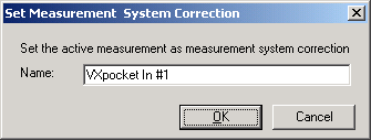
6.
Perform a measurement again. This should now be flat in the frequency domain.
Also inspect it in time domain it should be a very short peak (a so-called Dirac
pulse) at time 0 milliseconds.
Note: If you want to measure correct delay,
check if you sound card is capable of doing this. If not, you can use the
loop-back feature explained in the next section. Click the  button to set the delay
settings.
button to set the delay
settings.
7. Connect the usual equipment and perform measurements with and without the system correction and observe the difference.
If you measure using synchronization loop-back, you might experience a small tail at the very end of the impulse response (it can be seen if you plot the impulse response on a dB scale). This is a result of the correction filtering procedure. If this tail is less than 50 dB below the maximum of the impulse response, it should be nothing to worry about for most applications.
If  is checked, the relative gain of the system you are measuring
can be measured, even if no calibration has been performed. If the amplification
of the system you are measuring has increased 5 dB after you performed the
reference measurement, the peak of the impulse response and frequency response
curve will therefore be at 5 dB. The linear amplification may be displayed by
plotting for example the first part (it is given by the maximum) of the impulse
response using linear vertical axis. To plot the amplification in dB, do the
same using a logarithmic vertical axis, or plot the magnitude frequency
response.
is checked, the relative gain of the system you are measuring
can be measured, even if no calibration has been performed. If the amplification
of the system you are measuring has increased 5 dB after you performed the
reference measurement, the peak of the impulse response and frequency response
curve will therefore be at 5 dB. The linear amplification may be displayed by
plotting for example the first part (it is given by the maximum) of the impulse
response using linear vertical axis. To plot the amplification in dB, do the
same using a logarithmic vertical axis, or plot the magnitude frequency
response.
Once in a while you should verify that the measurement system correction is valid. Especially if you do not have control over your sound cards delay. You can test this by doing a loop-back measurement of your sound card (output connected directly to input).
 Contents
 Index
Index Search
 Previous
 Next
Next
